Central Water-Cooled Chiller
Plant for Shopping Mall

United Arab Emirates • Centralized Commercial Cooling Infrastructure

1,200 kWInstalled Cooling Capacity
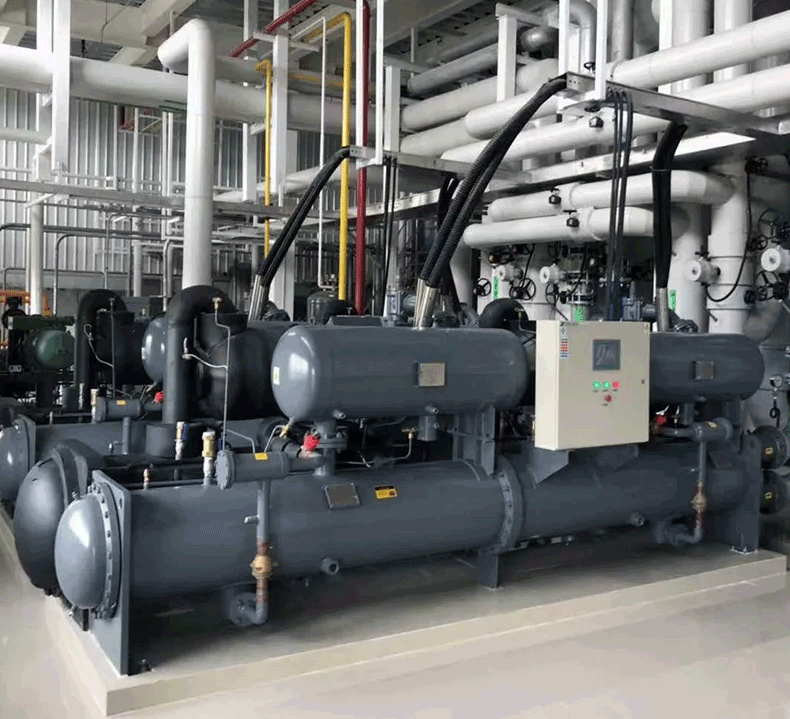
2Water-Cooled Screw Chillers
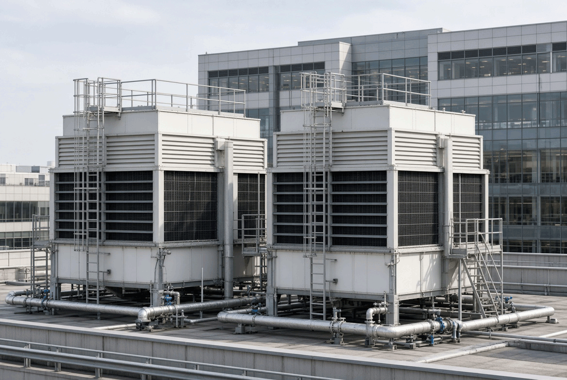
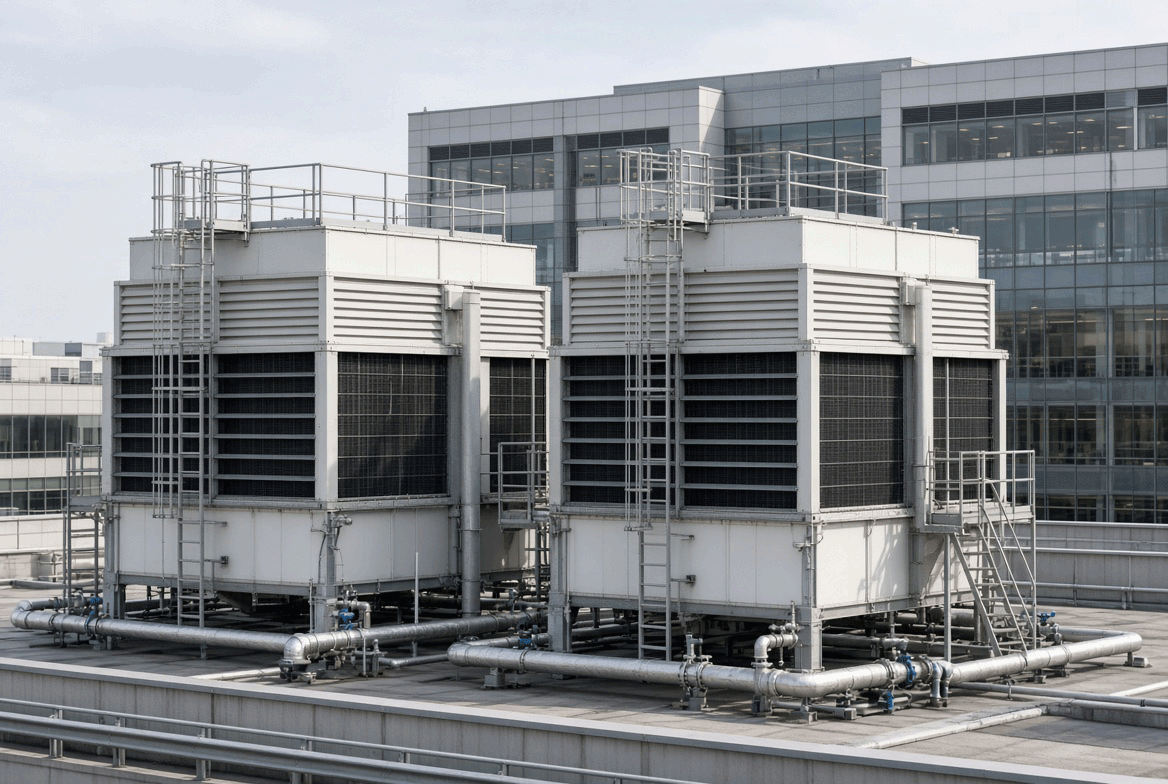
2Cooling Towers
24/7Commercial HVAC Operation
SYSTEM STATUS — OPERATIONAL
✓ Commercial HVAC ✓ Water-Cooled Chiller Plant ✓ Centralized Cooling ✓ PLC Plant Control
Lohabour UAE Shopping Mall Central Chiller Plant
1,200 kWCooling Capacity
2Chillers
2Cooling Towers
PLCControl
Engineering Brief

CustomerShopping Mall Operator (NDA)
IndustryCommercial HVAC
ApplicationCentralized Chilled Water Cooling — Shopping Mall HVAC Network
ENGINEERING OBJECTIVE

Shopping malls experience highly variable cooling demand throughout the day — occupancy, outdoor temperature, solar gains, retail activity, restaurants, lighting, and tenant equipment all influence the instantaneous cooling load. Lohabour designed a centralized water-cooled chiller plant with approximately 1,200 kW of installed cooling capacity, built around two water-cooled screw chillers connected to a centralized chilled water distribution network and a dedicated cooling tower heat rejection system. The two-chiller configuration allows the plant to stage cooling capacity according to demand rather than running the full installed capacity continuously, while primary and secondary pumping provides controlled chilled water distribution across the facility.

PROJECT SCOPE
  • ✓ Cooling load assessment
  • ✓ Water-cooled chiller selection and staging strategy
  • ✓ Cooling tower heat rejection design
  • ✓ Primary & secondary pump station design
  • ✓ Chilled water distribution network
  • ✓ PLC-based plant automation
  • ✓ Electrical commissioning
  • ✓ Site performance testing
View Full System Flow ↓

Central Plant Cooling Network

The full plant layout — heat rejection, generation, distribution, and return — with live flow direction.

Heat RejectionCooling Tower System (×2)
Thermal GenerationWater-Cooled Screw Chillers (×2)
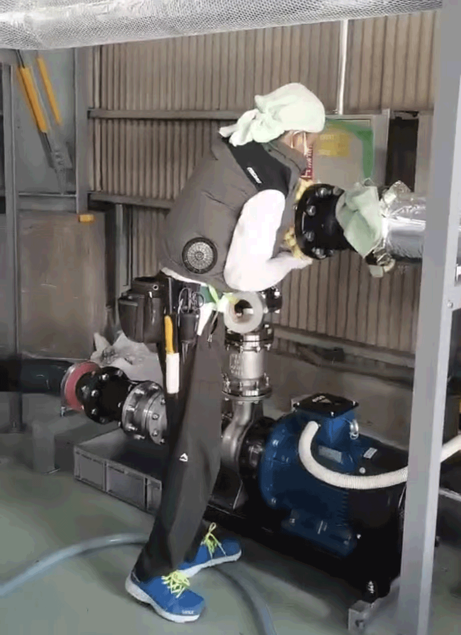
Hydraulic DistributionPrimary & Secondary Pump Station
Site UseRetail & Common Areas
Site UseRestaurants & Food Court
Site UseOffices & High-Occupancy Zones
ConsolidationChilled Water Return Header
↺ Back to Chillers

What Lohabour Was Called In To Fix

Shopping malls experience highly variable cooling demand throughout the day. Occupancy, outdoor temperature, solar gains, retail activity, restaurants, lighting, and tenant equipment can all influence the instantaneous cooling load — the plant needed to follow that variation efficiently rather than run its full installed capacity around the clock.

BEFORE — VARIABLE, UNSTAGED DEMAND

  • Highly variable cooling demand throughout the day
  • Reliance on cooling capacity with no staging flexibility
  • Distributed heat rejection increasing plant complexity
  • Manual coordination between chillers, pumps and towers

AFTER — CENTRALIZED, STAGED COOLING PLANT

1,200 kW
  • Automatic staged operation of two water-cooled chillers
  • Centralized cooling tower heat rejection
  • Primary & secondary hydraulic control
  • PLC-based plant sequencing

Not Equipment. Engineering.

01 Thermal Generation

Dual Water-Cooled Screw Chillers

Input

Continuously varying cooling demand from retail areas, common spaces, restaurants, offices and high-occupancy zones

Purpose

Generate chilled water using two water-cooled screw chillers, staged to match instantaneous building demand rather than running at full installed capacity continuously

Result

≈1,200 kW combined cooling capacity, with the flexibility to isolate a chiller for servicing without shutting down the plant

02 Heat Rejection

Cooling Tower System

Input

Warm condenser water carrying heat absorbed from the mall's chilled water circuit

Purpose

Reject heat to the atmosphere through evaporative cooling towers dedicated to the water-cooled chiller plant

Result

Continuous, reliable heat rejection capacity supporting sustained water-cooled chiller operation

03 Hydraulic Distribution

Primary & Secondary Pump Station

Input

Chilled water requiring separate circulation through the chillers and through the building distribution network

Purpose

Separate primary chiller circulation from secondary building distribution to maintain stable hydraulic conditions

Result

Stable chiller flow and flexible chilled water delivery across changing occupancy and building zones

04 Intelligence Layer

PLC Plant Control

Input

Continuously changing commercial cooling demand throughout the day

Purpose

Coordinate chiller staging, pump sequencing, cooling tower operation, and lead/lag rotation automatically

Result

Automatic equipment staging, improved operational control, alarm management, and reduced operator intervention

Engineering Parameters

EquipmentWater-Cooled Screw Chiller ×2
Cooling Capacity1,200 kW
Nominal Chiller Capacity≈600 kW per chiller
Cooling MethodCentralized Chilled Water
Heat Rejection2 Cooling Towers
Pump ConfigurationPrimary & Secondary Pumps
Control SystemPLC-Based Plant Automation
InstallationCentral Plant
OperationContinuous Commercial Operation

Hydraulic Cooling Cycle

Heat rejected to ambient air via cooling towers Cooling Tower Fans
🧊
Water-Cooled Screw Chillers
CompressorWater-Cooled CondenserExpansion ValveEvaporator
Primary Chilled Water Pumps
🏬
Shopping Mall AHUs / FCUs
Chilled Water Return Header
🧊
Back to Chillers
1,200 kWInstalled Cooling Capacity
StagedTwo-Chiller Operation

Layered Automation Stack

INTELLIGENCE

PLC Monitoring · Alarm Management · Equipment Protection

CONTROL

Chiller Staging · Pump Sequencing · Lead/Lag Rotation

HYDRAULICS

Primary & Secondary Pump Station · Chilled Water Header

THERMAL CORE

Water-Cooled Screw Chillers · Cooling Tower System

Central Plant Performance Dashboard

Design parameters, not live telemetry — figures reflect engineered targets for this system.

1,200 kW
Installed Cooling Capacity
2 Water-Cooled Chillers
2 Cooling Towers
PLC Plant Automation
24/7
Continuous Operation

Engineering Decisions

Why Two Water-Cooled Screw Chillers?

Challenge

Shopping mall cooling demand varies significantly with occupancy, outdoor temperature, operating hours, and tenant activity.

Decision

Install two water-cooled screw chillers, each rated at approximately 600 kW, for a combined installed capacity of approximately 1,200 kW.

Benefit

The plant can stage chiller operation to match actual demand, improving flexibility and avoiding unnecessary operation of the full installed capacity during lower-load periods.

Why Water-Cooled Chillers?

Challenge

A large commercial facility requires substantial cooling capacity while maintaining efficient centralized plant operation.

Decision

Use water-cooled screw chillers combined with a dedicated cooling tower heat rejection system.

Benefit

A centralized water-cooled architecture delivers high-capacity cooling with dedicated condenser heat rejection, well suited to large commercial HVAC installations.

Why Cooling Towers?

Challenge

The water-cooled chillers continuously transfer heat from the mall's chilled water system into the condenser water circuit.

Decision

Use dedicated cooling towers to reject condenser heat to the atmosphere.

Benefit

Provides the heat rejection infrastructure required for continuous operation of the centralized water-cooled chiller plant.

Why Primary & Secondary Pumping?

Challenge

The chiller plant and the mall distribution network have different hydraulic operating requirements.

Decision

Separate primary chiller circulation from secondary building distribution using dedicated pump stations.

Benefit

Improved hydraulic control, stable chiller flow, and flexible chilled water distribution across different building zones.

Why PLC Plant Automation?

Challenge

Commercial cooling demand changes continuously throughout the day.

Decision

Integrate chiller, pump, and cooling tower sequencing through a centralized PLC control system.

Benefit

Automatic equipment staging, improved operational control, alarm management, and reduced operator intervention.

What This System Delivers

Centralized CoolingA single cooling plant supplies chilled water throughout the shopping mall
Flexible CapacityTwo chillers allow cooling capacity to be staged according to actual building demand
Reliable Heat RejectionDedicated cooling towers provide continuous condenser heat rejection for the plant
Hydraulic ControlPrimary and secondary pumping provides controlled circulation between the plant and building network
Automated OperationPLC control coordinates chillers, pumps, and cooling towers according to operating conditions
Commercial ComfortThe centralized system supports stable indoor conditions across high-occupancy commercial areas

What Defines This System

Ratings below are a qualitative engineering assessment, not a measured benchmark — shown as a segmented meter rather than star icons to keep the framing technical.

CENTRAL
PLANT
Thermal Stability
Reliability
Automation
Flexibility
Maintainability
Energy Efficiency

Documented On Site

Engineering Principles Applied

Similar Applications

Office Towers & Business Parks Hotels & Hospitality Airports & Transit Hubs Mixed-Use Developments Large Retail & Leisure Facilities

Project At A Glance

EquipmentWater-Cooled Screw Chiller ×2 (≈600 kW each)
IndustryCommercial HVAC
LocationUnited Arab Emirates
Cooling Capacity1,200 kW
Cooling MethodCentralized Chilled Water
Heat Rejection2 Cooling Towers
Pump SystemPrimary & Secondary Pumps
ControlPLC Plant Automation
OperationContinuous Commercial HVAC Operation

Design Your Commercial
Cooling Architecture

Every commercial facility has a unique occupancy and load profile. Lohabour engineers analyze cooling demand variation, building zoning, and plant staging strategy to develop centralized chiller architectures engineered for efficiency and reliability.