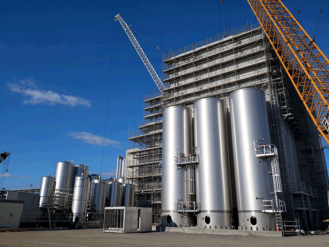
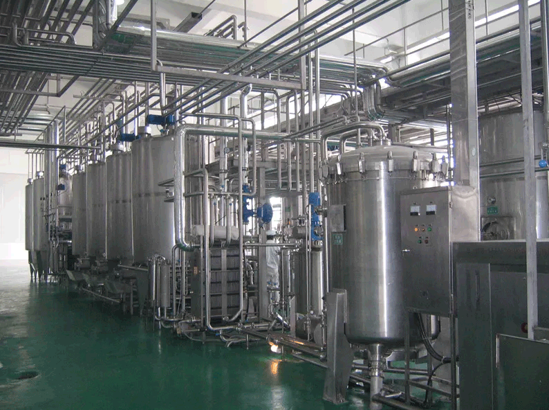
Precision Process Cooling System for
Dairy Processing Facility

New Zealand • Hygienic Milk Processing Cooling

350 kWCooling Capacity
2–6°CProcess Cooling Range
1Water-Cooled Industrial Chiller
24/7Continuous Process Cooling
SYSTEM STATUS — OPERATIONAL
✓ Dairy Processing ✓ Water-Cooled Chiller ✓ Hygienic Process Cooling ✓ Plate Heat Exchanger
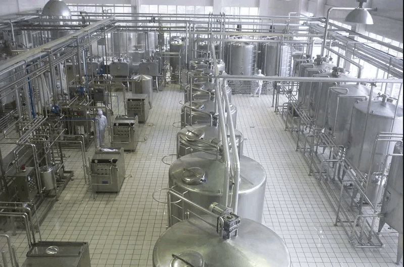
Lohabour New Zealand Dairy Processing Cooling Plant
350 kWCooling Capacity
2–6°CProcess Range
Cooling TowerHeat Rejection
24/7Operation
Engineering Brief

CustomerDairy Processing Facility (NDA)
IndustryDairy Processing
ApplicationMilk Processing — Centralized Water-Cooled Process Cooling System
ENGINEERING OBJECTIVE

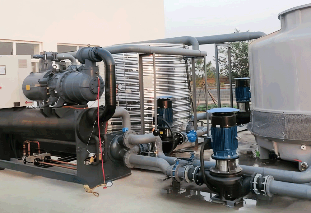
Milk processing operations require controlled thermal conditions throughout production, with cooling demand varying according to processing stages, production throughput, equipment operation, and product temperature requirements. Lohabour engineered a centralized process cooling plant with approximately 350 kW of cooling capacity to provide a stable chilled water source for the dairy processing system. The plant uses a water-cooled industrial screw chiller connected to a dedicated condenser-water circuit and cooling tower, while a stainless steel chilled water tank and process circulation pumps provide stable cooling distribution. A plate heat exchanger separates the central chilled-water system from the dairy process circuit, transferring heat efficiently while maintaining hydraulic separation between the refrigeration loop and the process side.

PROJECT SCOPE
  • ✓ Cooling load assessment
  • ✓ Water-cooled chiller selection and sizing
  • ✓ Cooling tower heat rejection design
  • ✓ Stainless steel chilled water tank integration
  • ✓ Plate heat exchanger design
  • ✓ Process cooling pump station
  • ✓ PLC-based automation
  • ✓ Site performance testing
View Full System Flow ↓

Process Cooling Network

The full plant layout — heat rejection, generation, distribution, and return — with live flow direction.

Heat RejectionCooling Tower
Thermal GenerationWater-Cooled Industrial Screw Chiller
Hydraulic DistributionProcess Cooling Pumps
Site UseMilk Processing Circuit
Site UsePlate Heat Exchanger Interface
Site UseDairy Production Equipment
ConsolidationChilled Water Return
↺ Back to Chiller

What Lohabour Was Called In To Fix

Milk processing operations require controlled thermal conditions throughout production. Cooling demand can vary according to processing stages, production throughput, equipment operation, and product temperature requirements — and the dairy process circuit needed to remain hydraulically separated from the central refrigeration system to protect hygienic processing standards.

BEFORE — VARIABLE, UNSEPARATED COOLING

  • Variable process cooling conditions
  • Direct dependence on process equipment cooling
  • Single, undifferentiated cooling circuit
  • Uncontrolled heat transfer between cooling and process sides

AFTER — ENGINEERED PROCESS COOLING PLANT

2–6°C
  • Controlled chilled water supply within a defined process range
  • Centralized 350 kW cooling plant
  • Hydraulically separated central and process circuits
  • Dedicated plate heat exchanger interface

Not Equipment. Engineering.

01 Thermal Generation

Water-Cooled Industrial Screw Chiller

Input

Continuous process cooling demand from milk processing operations and dairy production equipment

Purpose

Generate chilled water using a water-cooled industrial screw chiller connected to a dedicated condenser-water and cooling tower circuit

Result

≈350 kW of centralized cooling capacity supplying the process cooling system

02 Heat Rejection

Cooling Tower System

Input

Warm condenser water carrying heat removed from the refrigeration cycle

Purpose

Reject heat to the atmosphere through a dedicated condenser-water cooling tower circuit

Result

Continuous heat rejection capacity supporting sustained water-cooled chiller operation

03 Process Interface

Plate Heat Exchanger

Input

Chilled water from the central refrigeration circuit and warm return water from the dairy process circuit

Purpose

Transfer heat between the two circuits without mixing the fluids, keeping the process side hydraulically separated from the central cooling system

Result

Efficient heat transfer with process-side isolation, controlled heat transfer, and easier maintenance

04 Hydraulic Buffer

Chilled Water Tank & Process Pumps

Input

Changing chilled water demand as production equipment and process stages operate

Purpose

Provide hydraulic buffering and stable circulation through a stainless steel chilled water tank and dedicated process cooling pumps

Result

Stable chilled water availability and consistent flow through the plate heat exchanger during changing process demand

Engineering Parameters

EquipmentWater-Cooled Industrial Screw Chiller ×1
Cooling Capacity350 kW
Process Cooling Range2–6°C
Cooling MethodWater-Cooled Chilled Water
Heat RejectionCooling Tower
Buffer / StorageStainless Steel Chilled Water Tank
Process InterfacePlate Heat Exchanger
CirculationProcess Cooling Pumps
OperationContinuous Process Cooling

Hydraulic Cooling Cycle

Heat rejected to ambient air via cooling tower Cooling Tower Fan
🧊
Water-Cooled Industrial Screw Chiller
CompressorWater-Cooled CondenserExpansion ValveEvaporator
🛢
Stainless Steel Chilled Water Tank
🔄
Process Cooling Pumps & Plate Heat Exchanger
🥛
Dairy Processing Circuit
Return to Chiller
2–6°CProcess Cooling Range
24/7Continuous Operation

Layered Automation Stack

INTELLIGENCE

PLC Monitoring · Temperature Sensors · Alarm Protection

CONTROL

Automatic Temperature Control · Chiller Sequencing

HYDRAULICS

Process Cooling Pumps · Plate Heat Exchanger Interface

THERMAL CORE

Water-Cooled Industrial Screw Chiller · Cooling Tower

Process Cooling Performance Dashboard

Design parameters, not live telemetry — figures reflect engineered targets for this system.

350 kW
Cooling Capacity
2–6°C
Process Cooling Range
1 Cooling Tower
PLC Automated Control
24/7
Continuous Operation

Engineering Decisions

Why a Water-Cooled Industrial Chiller?

Challenge

The dairy facility requires approximately 350 kW of continuous process cooling within a controlled temperature range.

Decision

Use a dedicated water-cooled industrial screw chiller connected to a condenser-water cooling tower system.

Benefit

Provides centralized process cooling capacity with dedicated heat rejection suitable for a substantial industrial thermal load.

Why a Cooling Tower?

Challenge

The water-cooled chiller must continuously reject heat from the refrigeration cycle.

Decision

Connect the condenser side of the chiller to a dedicated cooling tower through a condenser-water circulation loop.

Benefit

Provides continuous atmospheric heat rejection and completes the water-cooled refrigeration cycle.

Why a Stainless Steel Chilled Water Tank?

Challenge

Dairy processing loads can change as production equipment and process stages operate.

Decision

Integrate a stainless steel chilled water tank into the process cooling circuit.

Benefit

Provides hydraulic buffering and helps stabilize chilled water availability during changing process demand.

Why a Plate Heat Exchanger?

Challenge

The central refrigeration circuit and dairy process circuit require controlled hydraulic separation.

Decision

Use a plate heat exchanger as the thermal interface between the chilled-water system and process circuit.

Benefit

Efficient heat transfer while maintaining separation between the central cooling system and the dairy process.

Why Dedicated Process Pumps?

Challenge

The dairy process requires controlled and reliable chilled water circulation.

Decision

Install dedicated process cooling pumps to circulate chilled water through the heat exchanger and process loop.

Benefit

Stable process flow, reliable heat transfer, and improved control of the cooling circuit.

What This System Delivers

Stable Process CoolingControlled chilled water provides consistent thermal conditions for milk processing operations
Centralized Cooling CapacityA dedicated approximately 350 kW industrial chiller provides the required process cooling capacity
Reliable Heat RejectionThe condenser-water circuit and cooling tower continuously remove heat from the water-cooled refrigeration system
Process SeparationThe plate heat exchanger separates the central chilled-water circuit from the dairy process circuit
Hydraulic StabilityThe stainless steel chilled water tank and dedicated process pumps help maintain stable circulation as production demand changes
Continuous OperationThe centralized cooling architecture is designed to support ongoing dairy processing and associated thermal loads

What Defines This System

Ratings below are a qualitative engineering assessment, not a measured benchmark — shown as a segmented meter rather than star icons to keep the framing technical.

PROCESS
COOLING
Thermal Stability
Reliability
Hygienic Separation
Automation
Maintainability
Energy Efficiency

Documented On Site

Engineering Principles Applied

Similar Applications

Beverage Processing Food & Beverage Manufacturing Brewery Process Cooling Pharmaceutical Production Cold Chain & Storage Facilities

Project At A Glance

EquipmentWater-Cooled Industrial Screw Chiller ×1
IndustryDairy Processing
LocationNew Zealand
Cooling Capacity350 kW
Process Cooling Range2–6°C
Cooling MethodWater-Cooled Chilled Water
Heat RejectionCooling Tower
Process InterfacePlate Heat Exchanger
StorageStainless Steel Chilled Water Tank
OperationContinuous Process Cooling

Design Your Process
Cooling Architecture

Every food and beverage process has a unique thermal and hygienic separation profile. Lohabour engineers analyze process cooling loads, temperature ranges, and hydraulic separation requirements to develop chilled water architectures engineered for reliability and product quality.