Plastic Injection
Cooling System

Malaysia • Automotive Injection Facility

180 kWProcess Load
34 m³/hWater Flow
±0.5°CTemp. Stability
24/7Production Mode
SYSTEM STATUS — OPERATIONAL
Lohabour Malaysia Plastic Injection
180 kWProcess Load
±0.5°CStability
24/7Production
34 m³/hWater Flow
Engineering Brief

CustomerConfidential — NDA Protected
IndustryAutomotive Injection Manufacturing
ENGINEERING OBJECTIVE

Maintain mold temperature stability within ±0.5°C across 18 injection molding machines during continuous 24/7 production.

PROJECT SCOPE
  • ✓ Thermal load calculation
  • ✓ Chiller selection
  • ✓ Hydraulic design
  • ✓ Heat rejection design
  • ✓ Control integration
  • ✓ Commissioning
View Full System Flow ↓

Factory Thermal Map

The full plant layout — heat rejection, generation, distribution, and return — with live flow direction.

Heat RejectionAir-Cooled Condenser
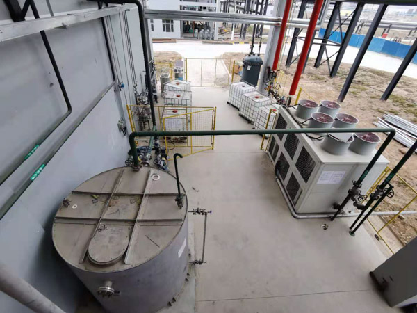
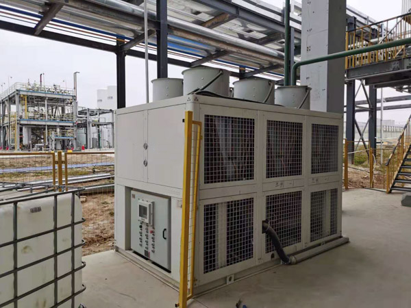
Thermal GenerationKAS-075 Screw Chiller · 200 / 238 kW
Hydraulic DistributionPump Station
Line AMachines 1–6
Line BMachines 7–12
Line CMachines 13–18
ConsolidationReturn Header
↺ Back to Chiller

What Lohabour Was Called In To Fix

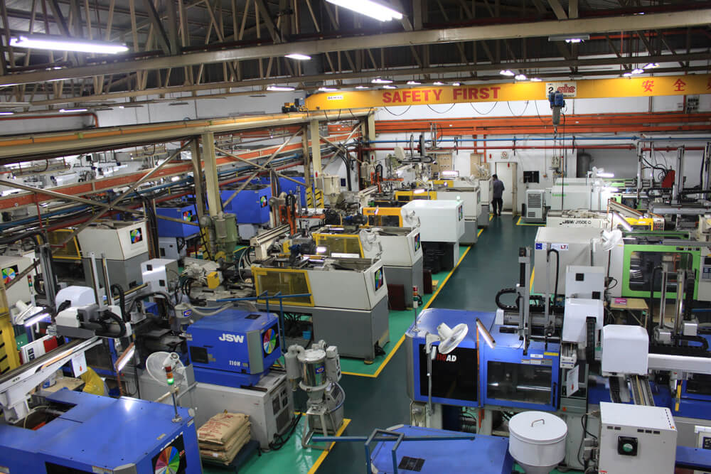
18 injection molding machines were each running their own standalone cooling unit — no shared control, no shared capacity, and no way to see the whole plant's thermal load at once.

BEFORE — 18 INDEPENDENT UNITS

  • 18 standalone chillers, one per machine, zero shared capacity
  • Mold temperature drifting during peak load
  • Cycle time variation across lines from inconsistent cooling
  • Oversized, energy-inefficient equipment with no central monitoring

AFTER — ONE ENGINEERED SYSTEM

±0.5°C
  • 180 kW centralized cooling across all 18 machines
  • 34 m³/h balanced flow through a single hydraulic network
  • One PLC, one control point, for the entire plant
  • 25% reserve capacity built into the header for future lines

Not Equipment. Engineering.

01 Thermal Generation

KAS-075 Air Cooled Screw Chiller

Input

180 kW process cooling demand

Purpose

Generate stable chilled water for centralized injection molding loop

Result

200 kW nominal cooling capacity, 238 kW maximum capacity

02 Process Stability

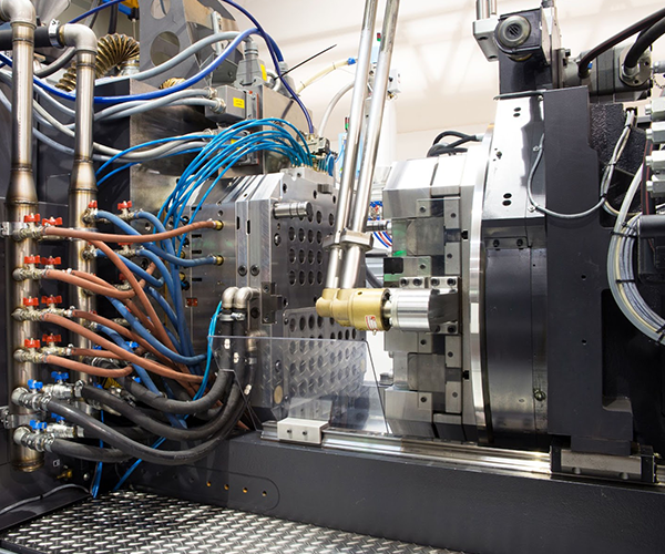
Mold Temperature Regulation Units

Input

18 individual mold circuits

Purpose

Fine temperature control between central chilled water loop and molds

Result

±0.5°C mold temperature stability

03 Heat Rejection

Air-Cooled Condenser

Input

Condenser heat load

Purpose

Reject heat to atmosphere efficiently

Result

Sized for 34°C design ambient, no derating

04 Intelligence Layer

PLC + Sensors

Input

Temperature & flow signals

Purpose

Monitor and optimize system operation

Result

Continuous automated control

05 Hydraulic Network

Pump Station

Input

34 m³/h required flow

Purpose

Balance circulation across 18 machines

Result

Even distribution, no dead legs

Hydraulic Parameters

Design Flow 34 m³/h
Operating Pressure 3–4 bar
Supply / Return Header DN80 (3")
Buffer Tank External — sized according to hydraulic volume
Expansion Tank Closed Loop — Sized by Volume
Pump Configuration External Pump Station
Pump Control Variable Speed Drive

Chilled Water Distribution Loop

Heat rejected to ambient air Axial Condenser Fans
🧊
KAS-075 Air-Cooled Screw Chiller
CompressorAir-Cooled CondenserExpansion ValveEvaporator
Pump Station
🔀
Distribution Header
🏭
18 Injection Molding Machines
Return Header
🧊
Back to Chiller
12°CSupply Water
18°CReturn Water

Layered Automation Stack

INTELLIGENCE

PLC · Sensors · Monitoring

CONTROL

Temperature Regulation · Flow Control

HYDRAULICS

Pumps · Pipes · Tanks

THERMAL CORE

Chiller · Air-Cooled Condenser

Thermal Performance Dashboard

Design parameters, not live telemetry — figures reflect engineered targets for this system.

±0.5°C
Temperature Stability
180 kW
Process Load
34°C
Design Ambient
25%
Expansion Margin
24/7
Operating Schedule

Engineering Decisions

Why Air-Cooled Architecture?

Challenge

Limited water infrastructure on site.

Decision

Air-cooled chiller system.

Benefit

Simplified installation, lower maintenance, faster commissioning.

Why Variable Flow Pumping?

Challenge

Production load changes throughout the day.

Decision

Variable frequency pump control.

Benefit

Optimized energy use with automatic load adaptation.

Why PLC-Based Control?

Challenge

Manual monitoring couldn't catch drift across 18 machines.

Decision

Centralized PLC with per-line sensors.

Benefit

Consistent ±0.5°C control with early fault detection.

Why Modular Line Design?

Challenge

Customer plans to add production lines within 2 years.

Decision

Header sized with 25% reserve capacity.

Benefit

Future lines connect without re-engineering the plant.

Why a Closed-Loop Circuit?

Challenge

Open systems risk contamination and water loss.

Decision

Fully closed, insulated stainless steel loop.

Benefit

Lower water consumption, consistent water quality.

What This System Delivers

18 injection molding machines connectedSingle centralized cooling loop, no per-machine units
180 kW process cooling load200 kW installed / 238 kW maximum, 12°C supply water
±0.5°C mold temperature stabilityHeld across all 18 machines during continuous operation
24/7 continuous productionNo scheduled cooling downtime
25% reserve capacityHeader sized for future line expansion without re-engineering
One PLC, one control pointCentralized monitoring replacing 18 separate control panels
34 m³/h balanced hydraulic networkSingle closed loop, no dead legs
Single centralized maintenance pointReplaces 18 individual service contracts

What Defines This System

Ratings below are a qualitative engineering assessment, not a measured benchmark — shown as a segmented meter rather than star icons to keep the framing technical.

THERMAL
CORE
Thermal Stability
Reliability
Automation
Scalability
Maintainability
Energy Optimization

Documented On Site

Engineering Principles Applied

Similar Applications

Electronics Manufacturing Packaging Factory Medical Injection Automotive Components Rubber Industry

Project At A Glance

LocationMalaysia
IndustryAutomotive Plastics
Process Cooling Load180 kW
Chiller ModelKAS-075
Installed Cooling Capacity200 kW
Maximum Cooling Capacity238 kW
Machines Connected18
Water Temperature12°C
ControlCentralized PLC
Operation24/7
Commissioned2024

Begin Your Engineering
Assessment

Every manufacturing process has a unique thermal profile. Before recommending any equipment, our engineers analyze process heat load, hydraulic requirements, ambient conditions, redundancy strategy, and future expansion plans to develop the most suitable cooling architecture.