Explosion-Proof Cooling
for Sand Mill Production

China • Lithium Battery Material Manufacturing

≈400 kWCooling Capacity
12Parallel Sand Mills
7°CSupply Water
24/7Continuous Operation
SYSTEM STATUS — OPERATIONAL
✓ Explosion-Proof Design ✓ Closed-Loop Cooling ✓ PLC Automated ✓ Battery Materials Industry
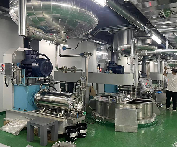
Lohabour China Lithium Battery Sand Mill
≈400 kWCooling Capacity
7°CSupply Water
24/7Operation
12Sand Mills
Engineering Brief

CustomerConfidential — NDA Protected
IndustryLithium Battery Materials
Hazard ClassificationExplosion-Proof Area
ENGINEERING OBJECTIVE

Maintain stable slurry temperature across twelve parallel sand mills, in a hazardous-area production environment, during continuous 24/7 wet grinding.

PROJECT SCOPE
  • ✓ Thermal load calculation
  • ✓ Explosion-proof chiller selection
  • ✓ Hydraulic design
  • ✓ Hazard classification compliance
  • ✓ PLC control integration
  • ✓ Commissioning
View Full System Flow ↓

Factory Thermal Map

The full plant layout — thermal generation, hydraulic buffering, parallel distribution, and return — with live flow direction.

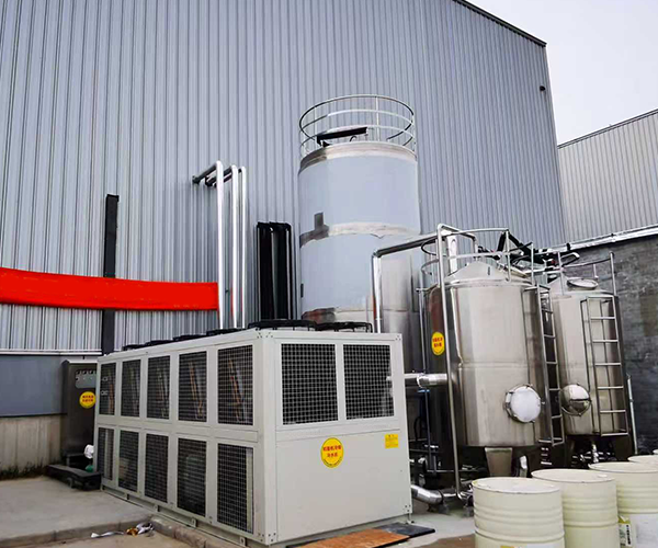
Thermal GenerationExplosion-Proof Air-Cooled Screw Chiller
Hydraulic BufferingInsulated Water Tank
Hydraulic DistributionDistribution Header
⑂ PARALLEL DISTRIBUTION — 12 LINES
Process Load12 Sand Mills (Parallel Grinding)
ConsolidationReturn Header
↺ Back to Chiller

What Lohabour Was Called In To Fix

Twelve sand mills grinding lithium battery slurry simultaneously convert mechanical energy into heat — in a hazardous area where cooling infrastructure has to meet explosion-proof requirements without ever interrupting 24-hour production.

BEFORE — UNCENTRALIZED COOLING

  • Independent cooling equipment per line, no shared capacity
  • Slurry temperature fluctuating during peak grinding load
  • Uneven cooling between mills affecting particle consistency
  • Higher maintenance workload across scattered units
  • Limited production scalability

AFTER — ONE ENGINEERED SYSTEM

7°C
  • Centralized hydraulic cooling across all 12 sand mills
  • Balanced parallel distribution, no uneven flow
  • One PLC + HMI, one control point, for the entire line
  • Expandable manifold architecture for future lines
  • Explosion-proof electrical configuration throughout

Not Equipment. Engineering.

01 Thermal Generation

KAS-120 Air-Cooled Screw Chiller

Input

≈400 kW process cooling demand

Purpose

Generate stable 7°C chilled water for a centralized 12-mill grinding loop, explosion-proof electrical configuration

Result

Semi-hermetic screw compressor, hazardous-area compliant

02 Hydraulic Buffering

Insulated Water Tank

Input

Varying production load across 12 mills

Purpose

Provide hydraulic buffering to stabilize supply temperature

Result

Stable 7°C supply held through load swings

03 Hydraulic Network

Primary Pump Station

Input

Continuous circulation demand, 12 parallel lines

Purpose

Maintain constant water circulation through the complete network

Result

Even distribution, no dead legs

04 Distribution

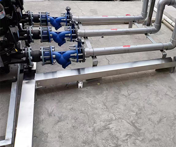
Stainless Steel Headers

Input

12 parallel sand mill circuits

Purpose

Balance supply flow and consolidate return water across every mill

Result

5 K controlled temperature differential

05 Intelligence Layer

PLC + HMI Control Cabinet

Input

Temperature, flow & pressure signals

Purpose

Automatically regulate supply temperature, monitor alarms and protect equipment

Result

Continuous automated control, explosion-proof compliant

Engineering Parameters

Cooling Capacity ≈400 kW
Equipment 12 Parallel Sand Mills
Supply Water 7°C
Return Water 12°C
Temperature Differential 5 K
Compressor Semi-Hermetic Screw
Control PLC + HMI
Operation Continuous 24/7

Hydraulic Cooling Cycle

Heat rejected to ambient air Explosion-Proof Condenser Fans
🧊
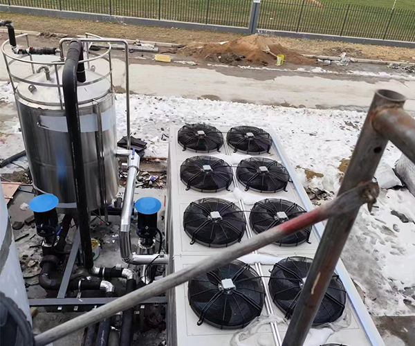
Explosion-Proof Air-Cooled Screw Chiller
Semi-Hermetic CompressorAir-Cooled CondenserExpansion ValveEvaporator
🛢
Insulated Water Tank
🔀
Distribution Header
12 Sand Mills (Parallel)
Return Header
🧊
Back to Chiller
7°CSupply Water
12°CReturn Water

Layered Automation Stack

INTELLIGENCE

PLC · HMI · Sensors

CONTROL

Temperature Regulation · Flow & Pressure Monitoring

HYDRAULICS

Pumps · Headers · Insulated Tank

THERMAL CORE

Explosion-Proof Chiller · Air-Cooled Condenser

Thermal Performance Dashboard

Design parameters, not live telemetry — figures reflect engineered targets for this system.

≈400 kW
Cooling Capacity
5 K
Temp. Differential
7°C
Supply Temperature
100%
Explosion-Proof Compliance
24/7
Operating Schedule

Engineering Decisions

Why Centralized Cooling?

Challenge

Twelve independent sand mills need consistent thermal performance without duplicated equipment.

Decision

One centralized hydraulic system supplies every production line.

Benefit

Simplifies maintenance and reduces equipment footprint.

Why a Closed-Loop Water Circuit?

Challenge

Continuous 24/7 grinding demands stable water quality without excessive consumption.

Decision

Fully closed-loop chilled water circuit.

Benefit

Minimizes water consumption while maintaining stable operating conditions.

Why a Parallel Distribution Network?

Challenge

Production load varies across the twelve mills throughout the day.

Decision

Balanced manifold distribution header feeding all lines in parallel.

Benefit

Every sand mill receives equal chilled water flow regardless of load.

Why Explosion-Proof Configuration?

Challenge

Battery slurry production may involve flammable solvents or combustible dust.

Decision

Explosion-proof electrical design across the entire cooling system.

Benefit

Compliant, safe operation in a hazardous production environment.

Why Modular Expansion?

Challenge

Production lines may increase as battery material output scales.

Decision

Manifold architecture designed for future integration.

Benefit

Additional sand mills connect without re-engineering the plant.

Why PLC Automation?

Challenge

Manual monitoring can't reliably track temperature, flow and pressure across 12 mills.

Decision

Centralized PLC + HMI with continuous monitoring.

Benefit

Real-time alarm management and automatic equipment protection.

What This System Delivers

Stable slurry temperature throughout productionMaintained continuously across the grinding cycle
Improved particle size consistencyMore uniform product quality batch to batch
Uniform cooling across all twelve sand millsBalanced parallel flow, no dead legs
Reliable 24-hour operationContinuous production with no cooling downtime
Reduced thermal stress on mechanical sealsLower wear on grinding equipment
Lower maintenance requirementsCentralized service point replaces scattered units
Improved process reliabilityConsistent thermal performance across shifts
Expandable hydraulic infrastructureManifold ready for future production lines

What Defines This System

Ratings below are a qualitative engineering assessment, not a measured benchmark — shown as a segmented meter rather than star icons to keep the framing technical.

THERMAL
CORE
Thermal Stability
Reliability
Automation
Scalability
Maintainability
Energy Optimization

Documented On Site

Engineering Principles Applied

Similar Applications

Chemical Processing Paint & Coatings Pigment Manufacturing Ink Production Ceramic Milling

Project At A Glance

EquipmentKAS-120 Air-Cooled Screw Chiller
IndustryLithium Battery Materials
ApplicationWet Grinding
Cooling MethodClosed-Loop Water Cooling
Distribution12 Parallel Sand Mills
ControlPLC Automation
LocationChina
Commissioned2021

Begin Your Engineering
Assessment

Every manufacturing process has a unique thermal profile. Before recommending any equipment, our engineers analyze process heat load, hazard classification, hydraulic requirements, ambient conditions, and future expansion plans to develop the most suitable cooling architecture.